I’m working on the packet box from a couple of posts below. One of the hardest parts was trying to decide how to bus-bar the power to the fuse block, until I remembered that I had a bunch of “piggyback disconnect” crimp connectors left over from my battery box project last year.
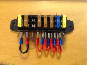 Et voila. The two fuses on the left are for the negative lines to the radio and the TNC. Probably overkill, but Yaesu ships their power cables with both lines fused, so what the hell.
The fuse block is going to go on the sidewall of the box instead of glued into the handle depression in the lid. The more I looked at that in the K4NHA go-box, the more I wondered how he planned to pull the fuses if one blew — it just looks awkward to me. And I don’t care if the box is 100% waterproof or not, although I’ll use some RTV around the bolt holes just because I have it. I’m also going to install a third bolt for a common negative post, and I’ll RTV that, too. All the positive lines feed directly from the fuse block so there’s no need for a common positive post at this point.
While I don’t have everything wired up yet, I’ve at least got the battery power to the main switch and wired through to the voltmeter.
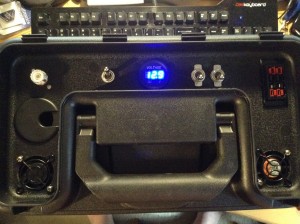 I decided against installing a dedicated RJ45 port and DB9 jack for the radio control head and the computer link to the TNC, and simply installed one of those plastic grommets furniture makers use to run cables through desktops. Cheap at Home Depot, and took the same 1-1/2″ hole that the fans did. I’ll just coil the cables up and store them inside the box between uses.
My plan was also to install a dual USB power port underneath the Powerpole connectors. I’m still going to do that, but I couldn’t get my hands on one in time to finish this up by the weekend. We have an ARES training session tomorrow featuring NBEMS over packet radio, and they said “bring your rig and we’ll help you set it up for NBEMS.” Since I have FLDIGI installed on the laptop that’s going with this go-box but haven’t quite figured out how to make it talk to the Kantronics TNC, I thought I’d take them up on the offer.
The main power switch is a 20A DPST toggle, to the left of the voltmeter. The two toggles to the right are 20A SPST and they are for switching the TNC and the fans separately from main power — for instance, I might want to run voice rather than packet, so there’s no reason in that case to have the TNC drawing power, or I might be outdoors in the cold with the box and not need the fans running. All the toggle switches came from Home Depot, for significantly less than I could have gotten them from the auto store or a ham supplier.
NHA also used a soldered bulkhead connector for his antenna. I prefer something more modular*, so I used a DX Engineering “Silver Plated Female SecureMount Bulkhead Connector Kit” and a DXE-532 right-angle connector on the inside of the box. I use the same combination on my main “home and go box” and it works pretty well there. I’ll use a short RG-8X jumper cable to get from the radio to the right-angle connector.
Here’s a shot of the inside of the lid so far. Remember I haven’t wired much of anything yet.
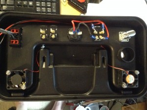 When I’m done, I’ll provide a wiring schematic. I notice that most hams don’t do that when they post projects, which is fine if you just want to brag about your mad 1337 skillz, but hell on those of us who might want to try building something similar. And mea culpa on me; I meant to do that for my battery box and I’ll probably do that one of these days, but I actually drew a schematic for this one before I started. It just needs a couple of revisions and cleanup before I can post it.
More later.
_____________________
* I can solder fine, thanks (those Y-connectors for the Powerpole unit are soldered and shrink-tubed). I just don’t like messing with soldered coax connections when I don’t have to.


